Did you know that 90% of warranty claims relating to LPHW unit heaters are rejected? Why? Because the source of the problem is rarely a manufacturing defect. Service statistics are clear – the “culprit” is usually human error at the installation stage.
The main problems fall into two categories:
- Hydraulics: The dominant issue here is a leaking heat exchanger. However, it does not fail on its own. The cause is typically over-tightening of the connection spigot (excessive force without counter-holding) or freezing of the heating medium (lack of anti-freeze protection).
- Controls and electrics: Burnt-out fans are frequently the result of incorrect controller wiring, absence of overcurrent protection, or operation in conditions for which the unit was not designed (e.g. the aggressive environment of a pig unit for a standard unit heater).
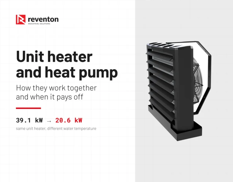
This guide will take you step by step through the installation process for HC and FARMER series unit heaters, drawing on hard data from the Technical Documentation.
Key information
- The two-spanner rule – ignoring counter-holding of the spigot is the most common cause of irreversible heat exchanger damage.
- Location – mounting too close to a wall or ceiling “chokes” the fan, drastically reducing motor service life.
- Flexible hoses – not optional but essential for protecting the installation against vibration.
- Preparation – air deflectors must be open (minimum 20%) before first start-up.
Before you begin: Transport and preparation for operation
Before you begin work, you must be aware of one absolutely critical rule, the breaking of which can destroy the unit whilst it is still in its box.
Never, under any circumstances, lift or carry the unit by the connection spigots! The protruding pipes are part of the delicate heat exchanger. Pulling on them can cause the internal solder joints to fail within the casing. Always handle the unit by the casing (EPP).
Preparation for installation: Open the box and check that the set is complete. Then prepare the necessary tools so you do not have to descend the ladder mid-task:
- Hydraulic spanners (absolutely two – one for tightening, one for counter-holding).
- Drill/screwdriver for mounting the bracket or threaded rods.
- Spirit level.
- Electrical tools (screwdriver, voltage meter, wire stripper).
STEP 1: Where and how to install the unit heater? (Wall vs ceiling)
The location of the unit determines whether the room will be warm or merely noisy. To allow the fan to draw in air freely, a clearance from the structure (wall or ceiling) must be maintained.
- Minimum 0.15 m – this is the absolute minimum for unobstructed airflow.
- If the unit is installed flush against a surface, the fan will be throttled, its output will fall, and noise levels and the risk of motor overheating will increase.
Installation height and jet reach: These parameters depend on the output of the unit. For the HC 70-3S model, for example:
- Wall: Installation height from 3 to 8 m (horizontal jet reach up to 18 m).
- Ceiling: Installation height from 5 to 9 m (vertical jet reach approx. 7 m). Note: In lower rooms use lower-output models to avoid causing discomfort (draughts) for people in the working zone.
Installation method:
- Swivel bracket: The most popular solution. Allows straightforward wall mounting and adjustment of the horizontal supply air angle.
- Mounting rods (M8): Ideal for ceiling suspension. Z-type hangers are used, or threaded rods screwed directly into rivet nuts in the casing.
IMPORTANT DETAIL: Before first start-up, set the air deflectors. They must be angled open by at least 20%. Starting the fan with the louvres closed creates enormous air resistance, which can damage the motor!
A cooling option is available for wall installation when the unit heater is supplied with chilled water. A condensate tray is then essential. Moisture condensing on the heat exchanger must be drained to the wastewater system. Bear in mind also that the heat exchanger must be perfectly clean when in cooling mode.

STEP 2: Hydraulic connection – how to avoid damaging the spigots?
This is the stage at which the greatest number of errors occur, resulting in loss of warranty.
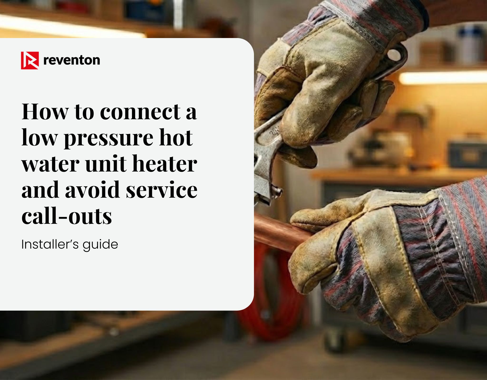
The “Two-Spanner Rule” is clear: when tightening a fitting onto the unit heater spigot, you must absolutely counter-hold the spigot with a second spanner.
- If you do not, the torque will be transmitted to the delicate copper pipes inside the heat exchanger.
- Result: Twisting of the manifold and a leak.
- Service verdict: Mechanical damage caused by the installer. Warranty voided.
Connection parameters and diagram
- Spigot diameter: standard 3/4″ (for HC and FARMER).
- Maximum medium parameters: 120°C and 1.6 MPa.
- Counter-flow arrangement: To achieve full heating capacity, connect the flow at the bottom and the return at the top of the spigot.

After pipe installation
- Fill the installation with water.
- Bleed the system (the unit heater has an air vent at the highest point of the manifold). An air-locked heat exchanger results in a drastic reduction in output.
- Carry out a pressure test.
Why should flexible hoses be used?
Rigid steel pipes are not ideal for fan-assisted units. Flexible hoses allow you to rotate the unit heater freely on its bracket. The fan generates micro-vibrations. Flexible hoses dampen these, protecting the heat exchanger from joint failures after several years of operation.
STEP 3: Electrical installation and controls (AC and EC motors)
The choice of controls depends on the type of unit heater. Check the rating plate.
Identify your motor:
- HC-3S / FARMER HCF IP54: Classic 3-speed motor (AC). Requires a simple controller or speed regulator.
- FARMER HCF IP66: Single-speed motor (AC) with enhanced ingress protection. The simplest control: ON/OFF.
- HC-EC: Modern electronically commutated motor (EC). Controlled by an analogue 0–10 V signal. Requires a different controller (e.g. HMI EC), but offers continuous speed regulation.
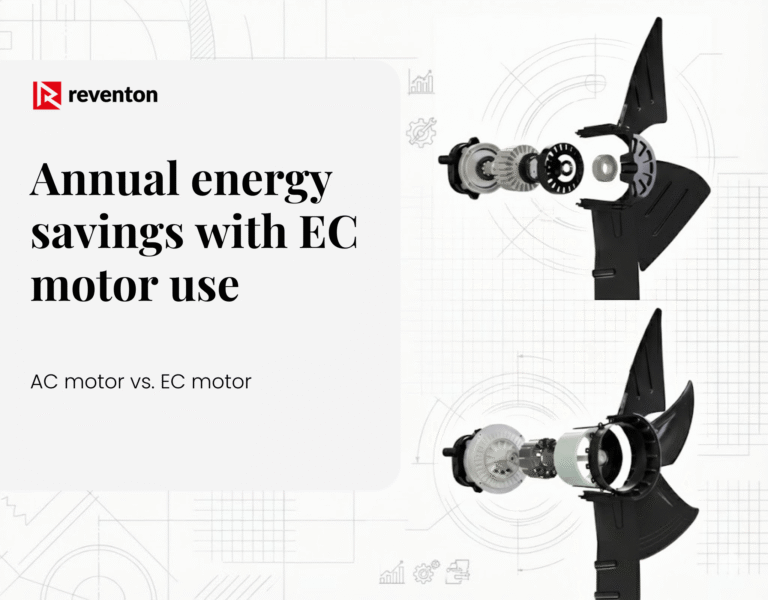
Want to find out more about the difference between AC and EC motors? See our case study:
Electrical safety: The installation must be carried out by a qualified electrician in accordance with best practice and local regulations.
- Earthing: The yellow-green conductor is fundamental to safety.
- Protection: Use a miniature circuit breaker and residual current device in the distribution board.
- Service switch: Installation of an isolating switch near the unit is recommended (for safety during servicing).
- Cables: Minimum cross-section is typically 2×1.5 mm² or 3×1.5 mm² (depending on the controller and distance).
Connection:
- Use only the manufacturer’s dedicated controls. “Improvising” with substitutes is a frequent cause of winding burn-out.
- Always verify wiring against the electrical diagram in the technical documentation.
- After start-up, check that the fan responds to changes in settings (speeds, temperature) and that it rotates in the correct direction!
How to maintain the unit? Servicing and heat exchanger cleaning
Dust and dirt on the heat exchanger act as an insulator – the unit heater may heat less effectively.
Standard cleaning (HC series): The recommended method is blowing with compressed air. Direct the jet along the fins (in parallel).
- Note: Do not use pressure washers or hard brushes. Aluminium fins are very delicate – bent fins will obstruct airflow.
Specific requirements for the FARMER HCF (aggressive environments): These models operate in poultry houses and pig units, where dust is greasy and corrosive.
- FARMER heat exchangers are coated with a special LCE (Gold Epoxy) coating.
- Combined with a motor to IP54 or IP66 ingress protection, this permits washing of the unit (with the precautions described in the manual), which is essential for maintaining hygiene in livestock buildings.
Post-installation checklist for the installer
Before packing away your tools and issuing the invoice, check these points. This is your assurance that you will not be called back for a warranty issue.
- Has a minimum clearance of 15 cm from the wall/ceiling been maintained?
- Are the air deflectors open (minimum 20–30%)?
- Were the spigots counter-held with “two spanners” when tightening?
- Has the installation passed a successful pressure test?
- Is the installation fully bled (valve at the highest point)?
- Does the fan rotate freely (not rubbing against the EPP casing or guard)?
- Are the fan and controller operating correctly at all speed settings?
Summary
Correct installation of an LPHW unit heater requires precision and adherence to several guidelines from the manual that are frequently overlooked. By applying the two-spanner rule, maintaining appropriate installation clearances, and using the correct controls, you ensure peace of mind and low running costs for the building owner, and a reputation as a professional who is recommended by word of mouth. It is better to spend an extra 15 minutes on installation than to lose hours on service call-outs.
Looking to select the ideal unit heater for your project or need technical support? View our products!